

Technologievorhaben
CastAutoGen

Objective:
Development of a hybrid process chain of casting and generation for use in automotive and vehicle construction
Partners: 
Duration: 01.05.2017 - 30.04.2019
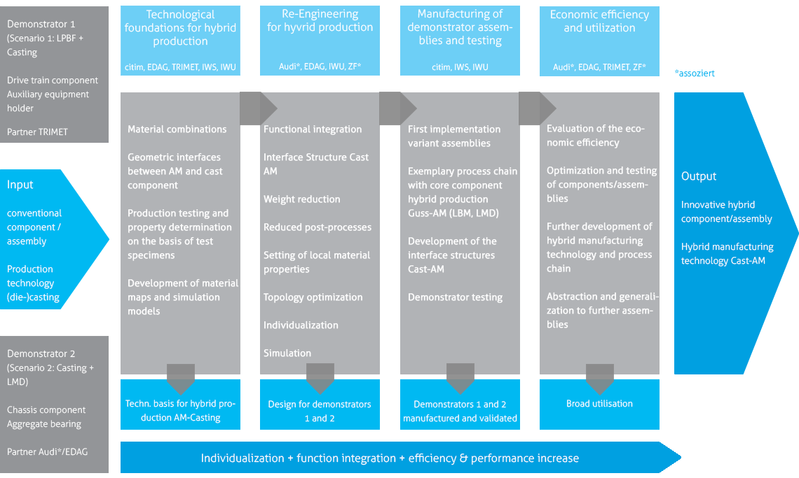
Development of a hybrid process chain of casting and additive manufacturing
Using demonstrators, two new, hybrid production routes (scenarios 1 and 2) were developed as examples. On the one hand, for the cast-on or overmoulding of laser-beam melted, complex components by die casting and, on the other hand, for the production of functional elements on unit die cast components by laser cladding.
The complex components (scenario 1) are heat exchangers made of materials with high thermal conductivity, additional component reinforcement, flow-optimized media channels and specific adapter geometries. The functional elements (scenario 2) on the unit die-cast component are individual, geometry-flexible joining elements and stiffening structures.
Implementation of the technology project in two scenarios [demonstrators]
The demonstrators were developed on the basis of two process combinations: Laser Powder Bed Fusion (LPBF) in combination with casting and casting and Laser Metal Deposition (LMD).
Results
In this project two demonstrators (scenarios) were successfully developed to combine the processes casting (aluminium die casting) and additive manufacturing (LPBF and LMD) to two new hybrid manufacturing process chains.
Scenario 1
The project objectives for scenario 1 are listed below:
| Objective | Requirement | |
|---|---|---|
| Casting or pouring of an additive manufactured high-performance heat exchanger | • Use of material with higher thermal conductivity, e.g. material containing copper • Compact, space-saving design combined with flow-optimised duct system |
|
| Casting of additive manufactured casting reinforcements | • Power-flow oriented design • Use of higher-strength materials for the reinforcement inserts, such as steel, as opposed to cast aluminium |
|
| Pouring of additive manufactured media channels | • Very small channel cross-sections that cannot be produced by casting • Complex duct systems can be realized (cannot be produced by machining after casting) |
|
| Casting of individual, additive manufactured inserts/adapter geometries | • Implementation of different variants with one die casting tool | |
All ambitious project goals from scenario 1 could be successfully implemented on the demonstrator "Holder Auxiliary Units" as shown in Figure 1 and Figure 2.
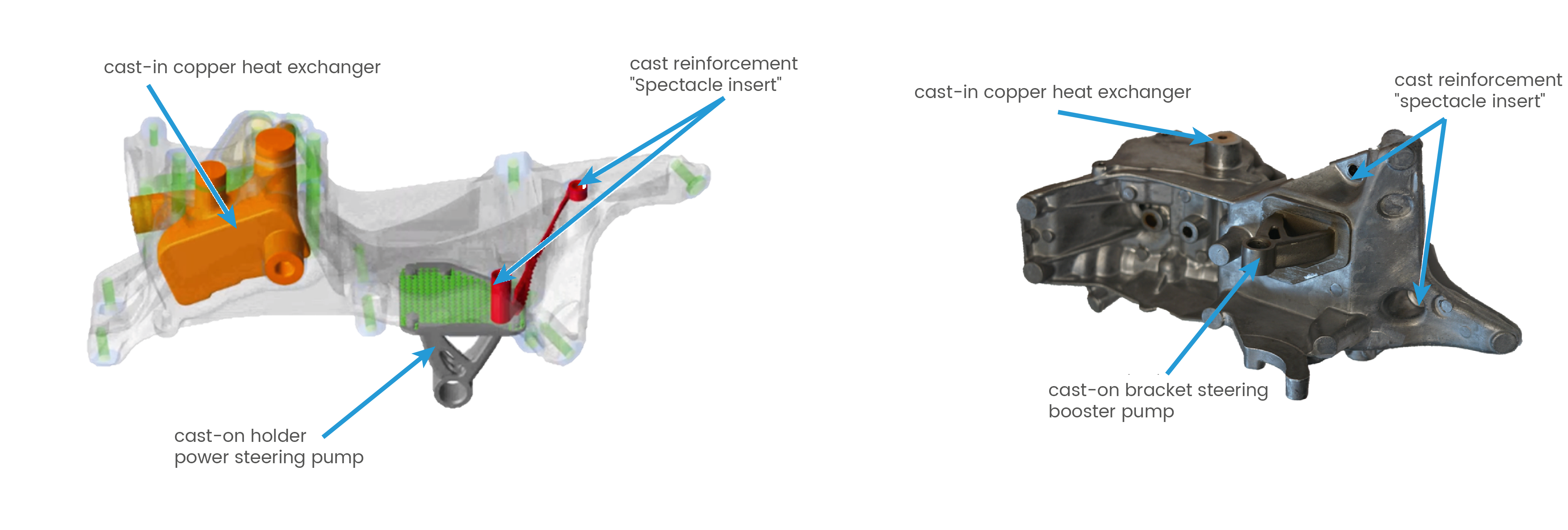
Figure 1: CAD representation of the demonstrator holder auxiliary units with the implemented project goals (source: EDAG)
Figure 2: Representation of the real demonstrator Halter auxiliary units with the implemented project goals (source: Fraunhofer IWU)
The conventionally mounted heat exchanger could be miniaturized with its function to integrate it directly into the holder auxiliary units. The complex media-carrying ducts were also designed as one unit with the heat exchanger. The heat exchanger was manufactured from a copper-bearing alloy using LPBF and cast in the die-casting process. An existing tool was modified in the project so that the heat exchanger with complex channels could be picked up and positioned as an insert. Figure 3 shows the development history of the heat exchanger, from the derivation of the working space to the final CAD design. Figure 4 shows two of the heat exchangers manufactured using LPBF. By selecting suitable casting parameters and measures to increase the dimensional stability of the channel cavities during casting, miniaturized high-performance heat exchangers with complex channels can be successfully cast, see Figure 5.
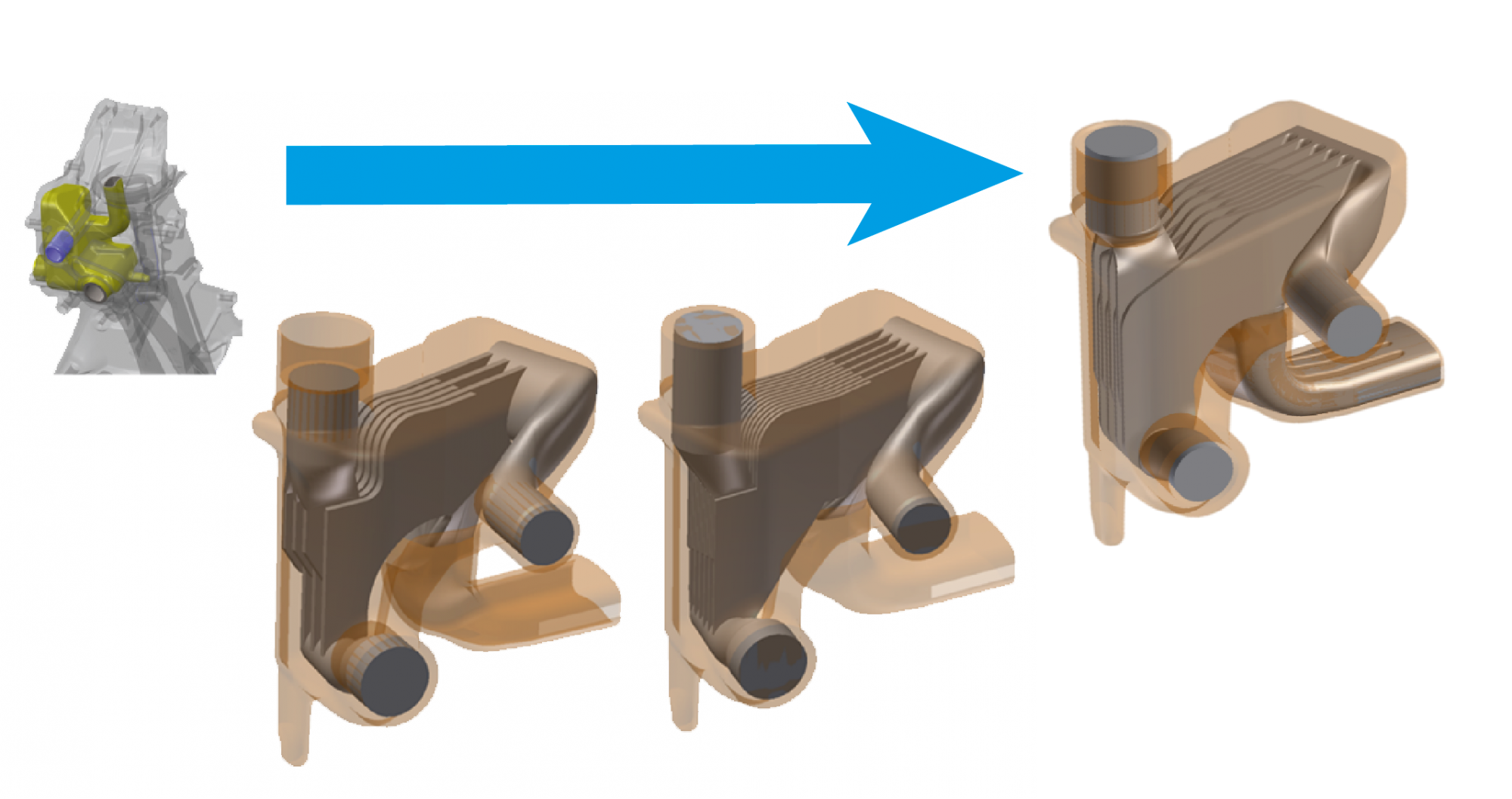
Figure 3: Development history of the miniaturized high-performance heat exchanger with complex channels (Source: Fraunhofer IWU)
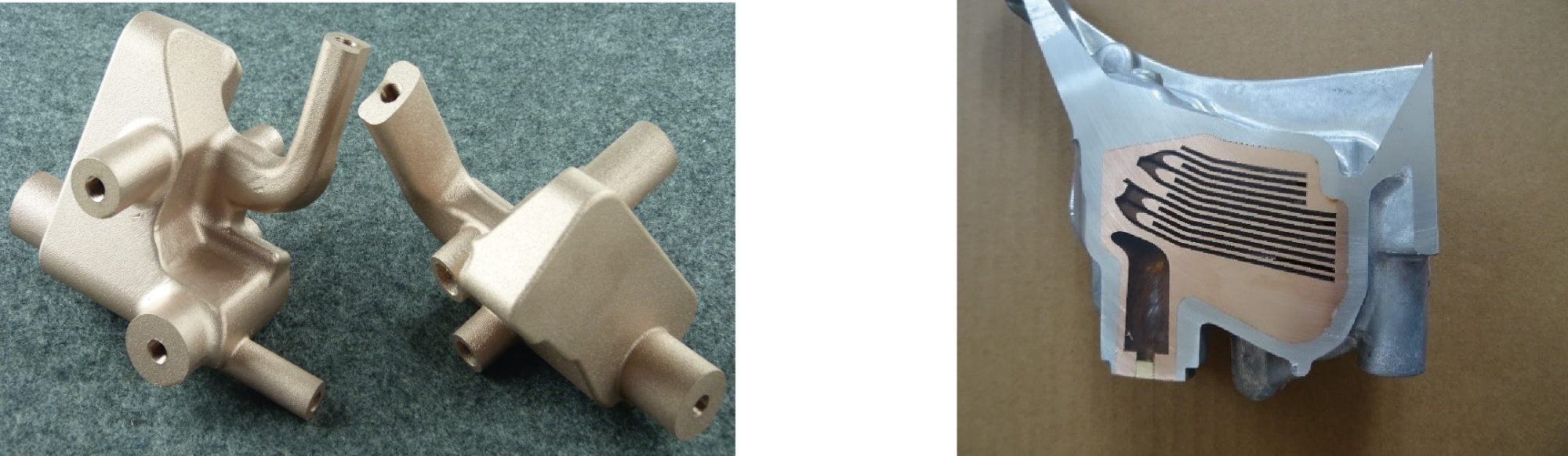
Figure 4: Miniature high-performance heat exchangers manufactured by laser beam melting with complex channels made of a copper-containing alloy (source: Oerlikon AM)
Figure 5: Die-cast high-performance heat exchanger (Source: Bohai Trimet)
The casting reinforcement (see Figure 6) was realized in the project between two bolt-on points of the demonstrator in order to achieve a higher stiffness between these points. The material stainless steel was chosen. Through extensive simulation and stiffness analyses, a correspondingly complex geometry could be developed and produced. The X-ray image in Figure 7 shows a cast-in component reinforcement in the demonstrator holder auxiliary units.
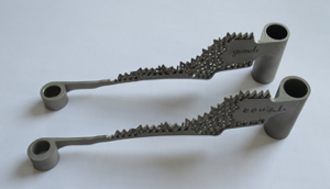
Figure 6: Laser beam melted component reinforcements made of stainless steel

Figure 7: X-ray image of a cast-in component reinforcement in the demonstrator (source: Bohai Trimet)
The variable adapter geometry was realized in the area of the holder for the power steering pump on the demonstrator. A standardized base plate made it possible to map an interface for the different holder variants in the die-casting tool. On the side of the adapter plate facing the die-cast component, an interface geometry was determined and validated by extensive preliminary tests, whereby the connection to the die-cast component is established by infiltration. During the development of the interface area, various surface modifications, infiltration structures and coating systems for improving the connection were extensively investigated. On the side facing away from the die-cast component, it was now possible to implement different receptacles for different applications such as e-mobility (see Figure 8).
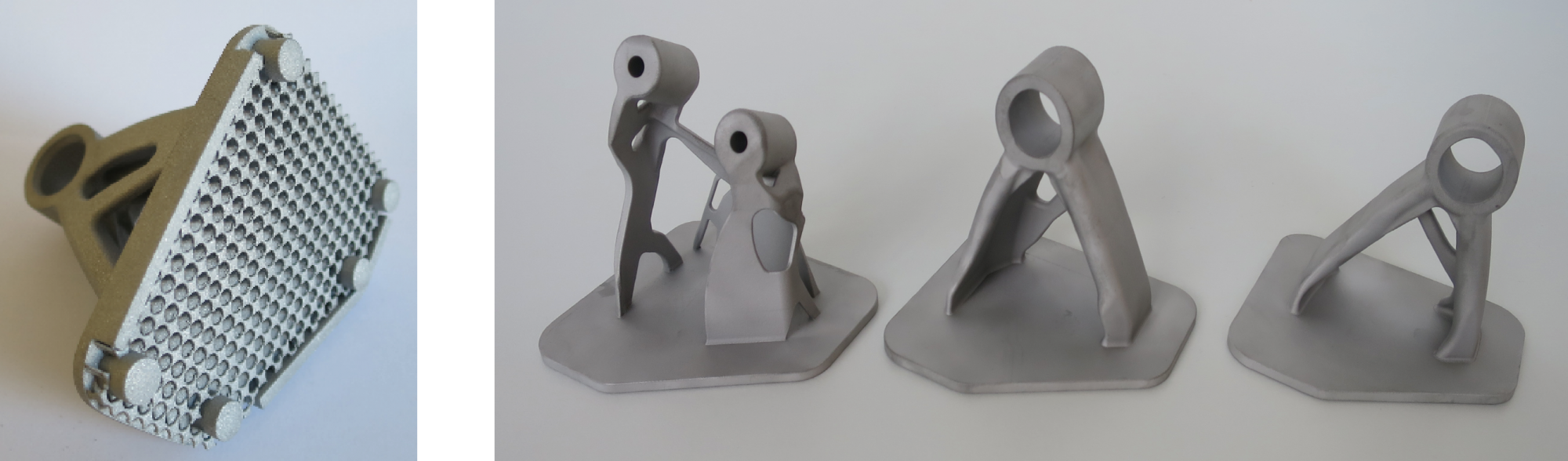
Figure 8: left: Insert "Holder Auxiliary Units" with infiltration structure; right: different geometry variants of the "Holder Power Steering Pump" on the standardized adapter plate (source: Fraunhofer IWU)
A corrosion test carried out with the complete demonstrator did not show any particular abnormalities.
Scenario 2
Project objectives for scenario 2 were as follows:
| Objective | Requirement | |
|---|---|---|
| Welded connection to the aluminium die-cast component | • Welding of a difficult to weld aluminium die casting alloy • Compressed gas inclusions in the casting |
|
| Higher strength, local stiffening from non castable material |
• Power-flow oriented design • Use of higher strength material for stiffening structure |
|
| Individual geometry ranges on standard die-cast components | • Personalization • Adaptation to special customer requirements |
|
| Individual, geometry-flexible joining elements | • Non-castable geometries (undercuts, demoulding direction, ...) • Individualisation (adaptation to e.g. different engine concepts, performance classes) |
|
In Scenario 2, too, all the project goals set were successfully implemented on the demonstrator "Aggregate Storage" (see Figure 9).
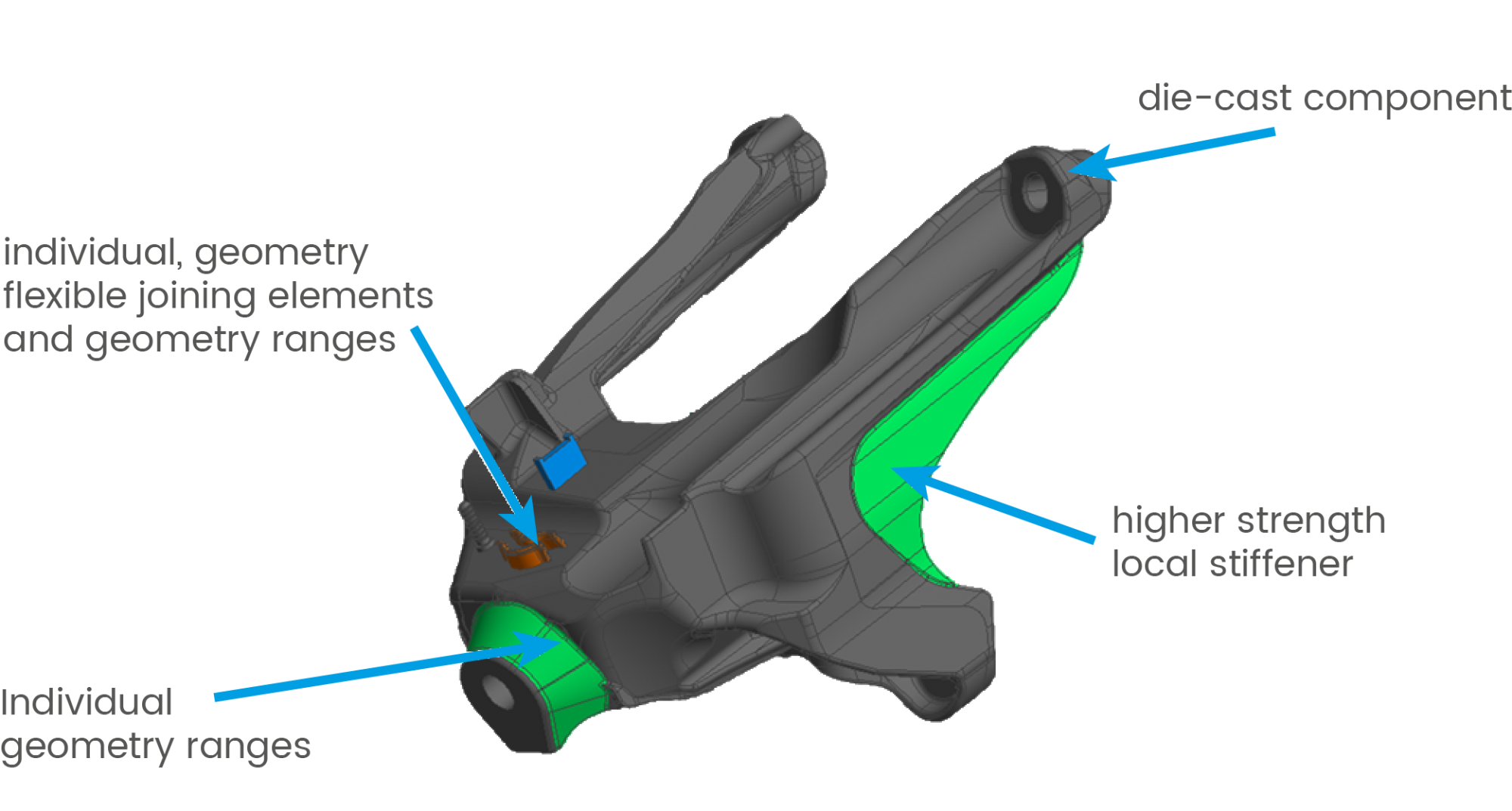
Figure 9: CAD representation of a demonstrator for aggregate bearings (grey) with implemented project goals (coloured) (source: EDAG)
At the beginning of the project, a CT analysis and metallographic examination was carried out on the substrate body of the demonstrator, which was manufactured by a partner outside the project consortium (see Figure 10). During the analysis, large pore accumulations were detected, which are not unusual for low-cost-oriented die casting. This porosity is not important for the application of the component, since it occurs specifically in component areas where it does not lead to any impairment of function or service life. In combination with additive manufacturing, however, it is often precisely these areas of the component that become interesting for connecting further geometries.
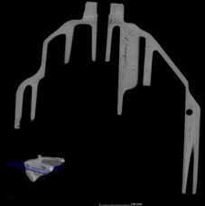
Figure 10: CT analysis of the AlSi12Cu1(Fe) die-cast component (source: YXLON)
In scenario 2, a parameter development was carried out for the additive build-up of the AlSi1MgMn alloy by means of LMD on ALSi12Cu1 die-cast substrate. At the end of the test series, the Fraunhofer IWS successfully developed a parameter set that reliably enables this setup. The parameter set was used in first further experiments to produce tensile, density and corrosion test specimens (see Figure 11). The material tests on the hybrid material combinations were all successfully passed and the results fully meet the requirements of the automotive industry.

Figure 11: LMD parameter tests and setup of the hybrid test specimens Scenario 2 (Source: Fraunhofer IWS)
Following the testing of the hybrid material combinations, the individual traversing strategies for the production of the various demonstrator geometries were developed. In cooperation with the project partner EDAG, structures were developed in advance to demonstrate the possibilities of the hybrid production route of casting and LMD assembly, such as joining elements that cannot be demolded in the conventional casting process (see Figure 12).
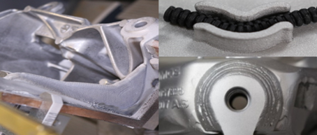
Figure 12: left local AlSi1MgMn stiffening on AlSi12Cu1 substrate, top right LMD joining element (tube clamp), bottom right individual geometry range (source: Fraunhofer IWS)
The individually tested functional geometries and joining elements were then combined in the final demonstrator. The demonstrator was finally examined by means of CT. As can be seen in Figure 13 on the left, pores are visible in the CT image in the transition area between the die-cast substrate body and the additive structure. These have their origin in the substrate body. During machining, the substrate material melts and the gases trapped in the casting process under high pressure expand, forming a pore seam in the substrate body. A strong reduction of the pore formation in the hybrid process could be achieved by vacuum-assisted die casting, since the proportion of forced dissolved gases in the casting is greatly reduced here. In addition, the traversing strategy of the LMD was adapted, in which the processing head is at a better angle to the substrate body (see Figure 13 right).

Figure 13: CT scans Demonstrator left and right Section with adapted setup strategy
This was made possible by better accessibility of the process head to the test substrate. Figure 14 shows the final demonstrator on the left and the vacuum-assisted cast substrate plate with the stiffening rib on the right, which was built up under adapted travel strategy.
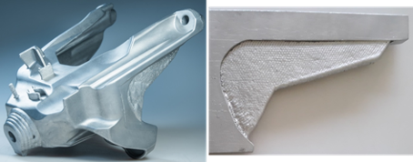
Figure 14: Demonstrator scenario 2 left and right Section with adapted setup strategy (Source: Fraunhofer IWS)
Would you like to know more? Under the following links you will find further publications on the CastAutoGen project:
• Hybrid manufacturing of fasteners in the CastAutoGen project using LMD on die-castings
• Additive Manufacturing and Casting - a Novel Hybrid Approach